The nodes find the flange. The drone checks what they cannot see.
Eight to ten laser nodes on masts watch a process station around the clock and name the leaking flange to a few centimetres. Where pipes hide a surface from every node, a drone goes and measures up close. A technician tightens the flange; the nodes confirm the fix. Ammonia first, methane next, on one photonic chip.
// simulation · Tremon model, not field data12 s loop
how it works · one leak, start to finish
Locate, check the blind spots, fix and confirm
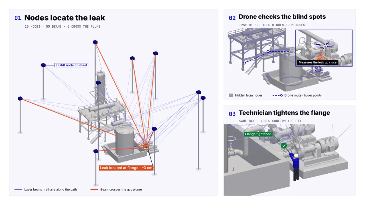
The loop above follows one leak at a process station. Every step below is what the video shows, in the same order. All numbers are Tremon model estimates, not measurements.
[1] Nodes locate the leak
Eight to ten laser nodes on masts (ten in this model) sweep their beams over the station. A beam that crosses the plume comes back weaker at the gas line. Where beams from three or four nodes cross, the system names the leaking flange, to about 3 cm in our model.
// video 0–5 s · 10 nodes, 55 beams, 6 cross the plume
[2] Drone checks the blind spots
About a quarter of the surfaces sit behind pipes and racks where no node can see them. A drone flies a short route to hover points under the racks and measures the leak up close, so the hidden part of the plant is checked too.
// video 5–10 s · ~25% of surfaces hidden from nodes
[3] Technician fixes · nodes confirm
The alarm names the flange, so the technician goes straight to it and tightens it the same day. The nodes keep watching: when the beams through that flange read clean again, the repair is confirmed and logged for LDAR reporting.
// video 10–12 s · same day, nodes confirm the fix
Fixed nodes do the watching. Monitoring is continuous and stays on the masts; the drone is an occasional check for surfaces the nodes cannot reach. It does not replace the network.
inside one node · one InP chip
One InP chip sends the beam and reads the gas
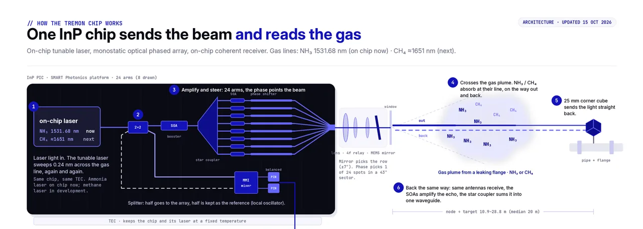
Each node is built around one indium-phosphide photonic chip. A tunable laser on the chip sweeps across the gas line. A 24-arm optical phased array points the beam by phase, with no moving parts in that axis. A small mirror picks the row. The same antennas collect the echo from a corner cube on the flange, and a coherent receiver on the chip mixes it with a sample of the laser to read the gas and the distance.
// architecture · updated 15 Oct 2026 · schematic9 s loop · steps 1–6
[a] Laser on the chip
The tunable laser sits on the same die. It sweeps 0.24 nm across the gas line again and again. Ammonia at 1531.68 nm (vacuum) is the first line in the design; a methane laser at 1650.96 nm (vacuum) would follow, on the same chip and the same temperature control.
[b] Steered by phase
A splitter keeps half the light as the reference. The rest is amplified and fed to 24 arms; their phase points the beam across a 43° sector, 24 spots per row. The mirror behind a relay lens picks the row.
[c] Same way back
A 25 mm corner cube on the flange sends the light straight back. The same antennas collect it, the amplifiers lift it, and the echo is mixed with the reference on the chip. One RF wire leaves the chip.
[d] Depth and distance from one sweep
The dip at the gas line gives the gas along the path in ppm·m. The same sweep is an FMCW chirp, so the beat frequency gives the distance to the surface that answered.
key numbers · Tremon model estimates and targets, not measured on a bench
≤10 ppm·m
NH₃ target in 1 s (bench gate)
1.15 ppm·m
CH₄ detection threshold (model, systematic floor)
~10–50 g/h
CH₄ per node, localised (model); ~1 g/h only on retro-reflector paths near the source — to be validated in controlled releases
0.17 s
per node: 12 targets × 11 ms; nodes run in parallel
2.6–3.5 cm
leak position with 3–4 crossing nodes
10.9–28.8 m
node to target in the simulated station (median 20 m)
Where it stands: research stage; no chip has been made. Its building blocks (lasers, amplifiers, phased arrays, mixers and balanced detectors on indium phosphide) exist at foundries today; whether they can share one die at the gas line is what we are researching, alongside interviews with LDAR experts on where such a network would help. Every figure here is our own calculation; the first bench node is what measures them. Schematic is illustrative.
gases · ammonia first, methane next
Ammonia first. Methane next. Any gas with a laser line after that.
The node reads a gas by the infrared line it absorbs. Ammonia (NH₃, 1531.68 nm) is the first line in the design: it is the lead gas for ammonia-fuelled ships, bunkering and SCR slip. Methane (CH₄, 1650.96 nm, vacuum) would come next, for leak detection and repair under Regulation (EU) 2024/1787. Gases in the same near-infrared band can share the chip design; mid-infrared gases need a different die.
Gas
Name
Laser line
Who asks for the number
NH₃ first
ammonia
1531.68 nm
ammonia-fuelled ships and bunkering; SCR slip under the IED
waste incineration; aluminium smelters; battery fire toxicity
SO₂ / NO / NO₂
sulphur and nitrogen oxides
5–7.3 µm
stack monitoring (IED, MCP); roadside air quality (Directive 2024/2881)
SF₆ / NF₃ / CF₄
F-gases: switchgear and fab gases
7.8–11 µm
Regulation 2024/573: switchgear, fab abatement, 2035 bans; magnesium casting
R-32, R-134a, R-125, HFO-1234yf
F-gases: refrigerants and blends
7.5–9.2 µm
Regulation 2024/573 Art. 5–6: fixed leak detection; reefers, rail HVAC, data centres, MAC
C₄F₇N / C₆F₁₂O / HFC-227ea
F-gases: SF₆ substitutes, fire suppression
4.4 / 7.5–9 µm
new MV switchgear; fixed fire-suppression leak checks (2024/573)
Line positions from the HITRAN database and published band tables; which gases ship, and when, follows the roadmap on our partners page.
interactive 3D
Turn the plant. See the mesh from every angle.
Drag to rotate, scroll to zoom. The model auto-rotates until you touch it; double-click to reset. The glowing markers show where beams cross the gas — the moment the system reads the gas.
EU rules are turning methane detection from good practice into an obligation
Regulation (EU) 2024/1787 (the Methane Regulation) tightens leak-detection-and-repair and measurement-and-reporting across oil, gas and biomethane; the timeline runs through the late 2020s. Today most operators still survey by hand a few times a year. Continuous, self-locating detection is the gap between what the rule will demand and what a handheld survey can deliver — and it is the gap we are researching, through interviews with LDAR operators and experts. Read the LDAR rules →
A mesh of laser nodes, reading gas along every beam
In the concept we are researching, chip-scale laser nodes ring the plant and sweep beams over its pipes, walls and reflectors. Gas on a beam's path absorbs a known infrared line; edge-AI turns the whole mesh of readings into one answer — is there a leak, where, how big — updated continuously. Nothing here is built yet; we are testing the idea with LDAR experts first.
[1] Ring the plant
Low-power laser nodes on existing structures form a self-surveying mesh — no trenching, no fixed sample lines.
[2] Read every path
Each beam measures gas absorption along its line; many crossing paths cover the volume, not just points.
[3] Locate & name
Edge-AI inverts the mesh to the source: which joint, how high, how fast.
[4] Alert & log
Continuous record for MRV/LDAR reporting; flags a leak and where it is to your control room — hands-free between surveys.
what it is — and isn't
An honest picture of where this stands
It is a network of fixed nodes that names which flange is leaking from continuous readings — the answer an operator acts on.
The drone does not replace the nodes. It is an occasional close-up check of the surfaces no node can see; continuous duty stays on the masts.
The video is a simulation on a model process station. Beams, plume and drone route are computed; it is not a field recording.
Every number is a model estimate. This is research: no chip has been made and nothing on this page is measured on a bench. It is not a product.
No. This is research: no chip has been made and nothing on this page is measured on a bench. Every number is a model estimate.
Does the drone replace the nodes?
No. Fixed nodes do the continuous monitoring; the drone is an occasional close-up check of the surfaces no node can see.
Which gases come first?
Ammonia at 1531.68 nm (vacuum) is the first line in the design; a methane laser at 1650.96 nm (vacuum) would follow.
Is the video a field recording?
No. It is a simulation on a model process station: beams, plume and drone route are computed.
Collaborate with us
// ldar network · research collaboration
Let's research this together
We are researching laser nodes that sweep a plant continuously and name the leaking component, with a drone for what they cannot see. We want to test where that would help with the people who find and repair leaks today.
// who we look for
Plant, terminal and gas-network operators
LDAR service providers and survey teams
MRV, LDAR and emissions-reporting experts
Research groups in lidar, photonics and gas dispersion
// what collaboration means
Expert interview — 30 minutes on how you handle leak detection and repair on your sites today, and where a new kind of sensor would — or would not — help.
Feasibility study or pilot — We scope your use case together — your gas, site or system — and test whether the concept fits. A pilot follows once there is hardware to put on site.
Joint research or grant consortium — Partner with us in a joint research project or an EU or national grant consortium on continuous, self-locating methane and ammonia leak detection.